adam wang

Forum Posts
-
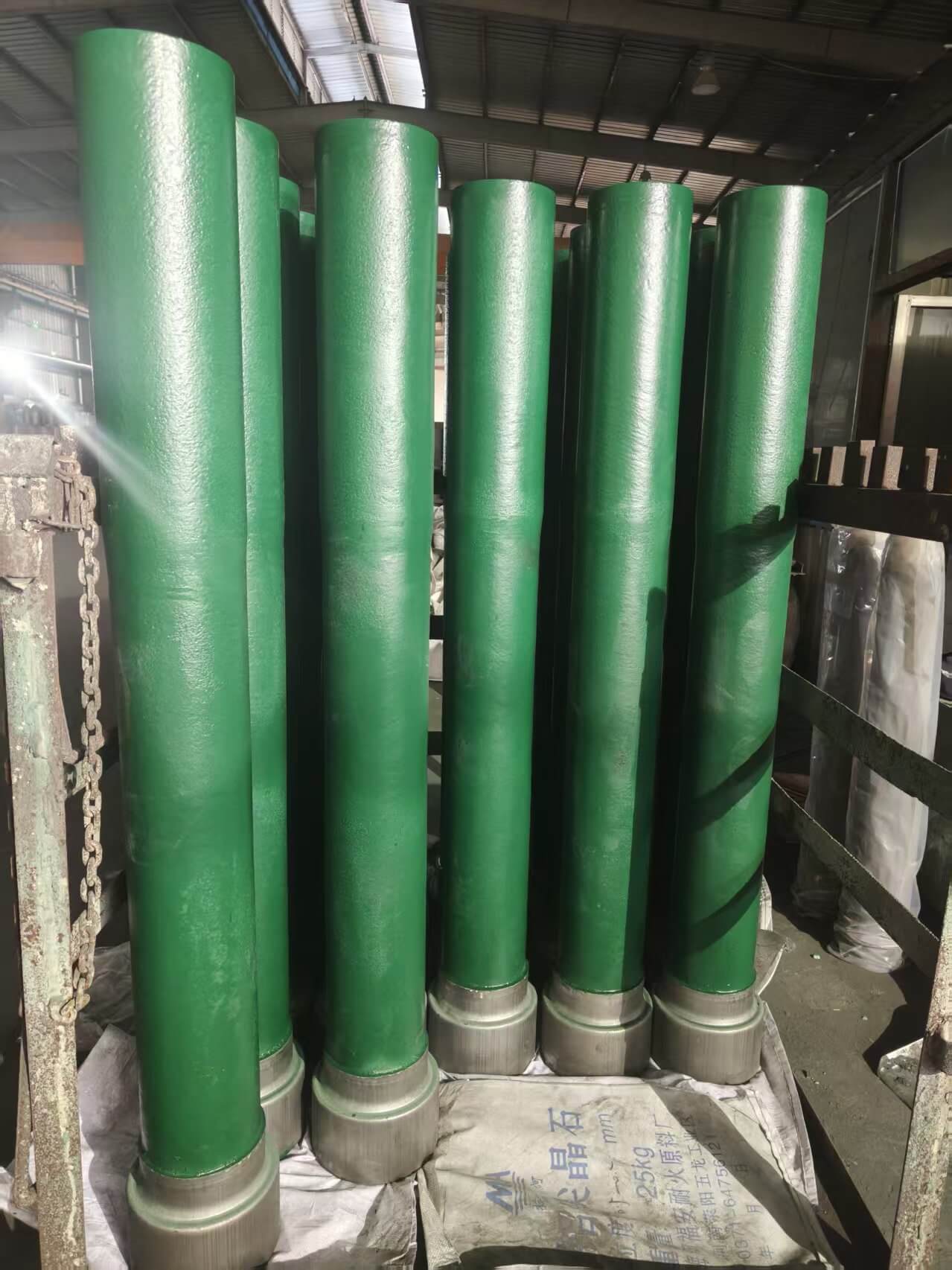
Posted in the topic Problems of Slide Gate Plates in Steelmaking in the forum News and AnnouncementsFebruary 5, 2026 12:39 AM PST
1. Introduction
The slide gate plate system is one of the most critical flow-control technologies used in modern steelmaking, particularly in ladle metallurgy and tundish operations. Its primary role is to regulate or completely shut off the flow of molten steel under extremely harsh conditions, including temperatures above 1600 °C, high ferrostatic pressure, chemical attack from slag and steel, and severe thermal shock. Despite its robust design and widespread industrial adoption, the slide gate plate is subject to a variety of operational problems that can negatively affect safety, casting stability, steel cleanliness, and refractory consumption.Understanding the problems associated with slide gate plates is essential for engineering students because these problems reflect the complex interaction between materials science, fluid mechanics, thermodynamics, and mechanical design. This article systematically analyzes the most common slide gate plate problems, explains their root causes, and discusses practical engineering countermeasures used in steel plants.
2. Overview of Slide Gate Plate Operation (Context)
A slide gate system typically consists of two or three refractory plates with aligned or misaligned bores. During operation:Molten steel flows through the aligned holes under ferrostatic pressure.
The sliding motion adjusts the flow rate or stops it entirely.
Plates are exposed simultaneously to molten steel, slag, mechanical friction, and temperature gradients.
Because the slide gate plate functions at the interface of liquid metal flow and mechanical motion, it is especially vulnerable to combined failure mechanisms.3. Erosion and Corrosion of Slide Gate Plates
3.1 Nature of the Problem
One of the most common and unavoidable problems of slide gate plates is erosion and corrosion, particularly around the bore area. Over time, material loss enlarges or deforms the bore, leading to unstable flow or leakage.3.2 Causes
High-velocity molten steel flow
Chemical dissolution by aggressive slags
Calcium-treated steels, which increase chemical reactivity
Long casting sequences without plate replacement
3.3 Consequences
Increased flow rate beyond control
Irregular steel stream
Shortened plate service life
Increased risk of steel leakage
3.4 Engineering Perspective
From a materials engineering standpoint, erosion is governed by fluid velocity and shear stress, while corrosion depends on slag chemistry and refractory composition. Alumina–carbon plates resist wetting but are vulnerable to oxidation; zirconia-containing plates resist erosion but are costly.4. Thermal Shock Cracking
4.1 Description of the Problem
Thermal shock cracking occurs when the slide gate plate experiences rapid temperature changes, especially during ladle opening or emergency shutdowns.4.2 Causes
Rapid heating from ambient temperature to molten steel temperature
Uneven preheating
High thermal expansion mismatch between phases
Poor plate thickness design
4.3 Typical Crack Patterns
Radial cracks from bore edge
Transverse cracks across the plate
Surface spalling
4.4 Impact on Operation
Cracked plates may:Lose sealing integrity
Allow steel penetration
Fail catastrophically under pressure
Thermal shock resistance is therefore a key design criterion in slide gate plate development.5. Steel Penetration and Plate Jamming
5.1 What Is Plate Jamming?
Plate jamming refers to the inability of the lower plate to slide smoothly. This is one of the most dangerous slide gate problems because it can prevent emergency shut-off.5.2 Root Causes
Steel penetration into microcracks
Slag infiltration between plates
Inadequate surface finish
Excessive plate wear
5.3 Metallurgical Mechanism
Once molten steel penetrates the refractory matrix, it solidifies during cooling, mechanically locking the plates together. This phenomenon is particularly severe in plates with poor oxidation resistance or low carbon content.5.4 Safety Implications
Loss of flow control
Inability to stop steel flow
Increased risk of breakout or ladle failure
6. Leakage Between Slide Gate Plates
6.1 Description
Leakage occurs when molten steel escapes through the interface between plates instead of flowing through the bore.6.2 Main Causes
Uneven plate wear
Poor plate alignment
Warping due to thermal stress
Inadequate contact pressure
6.3 Engineering Consequences
Steel dripping under the ladle or tundish
Severe safety hazards
Accelerated oxidation of surrounding equipment
Leakage is often an early warning sign of deeper refractory or mechanical problems.7. Nozzle Clogging Interaction
7.1 Relationship Between Slide Gate Plates and Clogging
Although clogging is commonly associated with submerged entry nozzles, slide gate plates play a role in clog formation due to flow disturbances at the bore exit.7.2 Causes
Alumina inclusion buildup
Reoxidation products
Low steel temperature
Poor bore geometry
7.3 Effects
Reduced flow rate
Unstable steel stream
Excessive sliding motion to compensate, accelerating wear
This interaction highlights the importance of integrated design between slide gate plates and nozzles.8. Oxidation of Carbon-Containing Plates
8.1 Problem Description
Most modern slide gate plates contain carbon to improve thermal shock resistance and reduce wettability. However, carbon oxidizes readily at high temperatures.8.2 Causes of Oxidation
Exposure to air during preheating
Long holding times
Poor antioxidant formulation
8.3 Consequences
Increased porosity
Reduced mechanical strength
Accelerated erosion
Higher risk of steel penetration
This is a classic trade-off in refractory engineering between performance and durability.9. Mechanical Wear and Friction Damage
9.1 Sliding Wear
Repeated sliding under high contact pressure causes abrasive wear at the plate interface.9.2 Factors Influencing Wear
Plate surface roughness
Contact pressure
Sliding frequency
Presence of hard inclusions
9.3 Engineering Impact
Reduced sealing performance
Increased actuation force
Shortened campaign life
10. Installation and Alignment Problems
10.1 Misalignment Issues
Improper installation can cause:Uneven wear
Biased flow
Localized overheating
10.2 Engineering Responsibility
From a systems engineering perspective, slide gate performance depends not only on material quality but also on:Frame stiffness
Actuator precision
Maintenance discipline
11. Summary Table: Major Slide Gate Plate Problems
ProblemMain CauseOperational RiskErosion & corrosionHigh flow, aggressive slagLoss of flow controlThermal crackingRapid heatingPlate failurePlate jammingSteel penetrationEmergency shut-off failureLeakagePoor sealingSafety hazardOxidationCarbon burnoutReduced lifeMechanical wearSliding frictionUnstable operation12. Engineering Countermeasures and Solutions
12.1 Material Optimization
Use alumina–carbon with optimized carbon content
Add antioxidants (Al, Si, B₄C)
Use zirconia inserts for high-wear zones
12.2 Design Improvements
Optimized bore geometry
Improved plate flatness
Three-plate systems for load distribution
12.3 Operational Best Practices
Proper preheating procedures
Controlled sliding frequency
Monitoring plate wear during casting
12.4 Automation and Monitoring
Modern steel plants increasingly use:Hydraulic slide gate systems
Wear monitoring
Predictive maintenance algorithms
13. Educational Importance for Engineering Students
For engineering students, slide gate plate problems provide real-world examples of:Multiphysics failure mechanisms
High-temperature materials behavior
Interaction between design and operation
Safety-critical engineering systems
Understanding these problems builds the foundation for solving complex metallurgical engineering challenges.14. Conclusion
Slide gate plates are indispensable components in steelmaking, but they operate under extreme conditions that inevitably give rise to complex and interrelated problems. Erosion, thermal shock, jamming, leakage, oxidation, and mechanical wear are not isolated issues but manifestations of coupled material, thermal, and mechanical phenomena.A systematic understanding of slide gate plate problems enables engineers to improve refractory design, optimize operating practices, and enhance safety and steel quality. For engineering students, mastering these concepts is essential for bridging theory and industrial practice in modern steelmaking.
-
Posted in the topic How to Avoid Cracking of Monoblock Stopper Rods in Continuous Casting in the forum News and AnnouncementsDecember 29, 2025 5:12 AM PST
1. Introduction
The monoblock stopper rod is a critical flow-control refractory component used in modern continuous casting operations. Installed in the tundish, it regulates molten steel flow into the submerged entry nozzle (SEN) by precise vertical movement. Compared with traditional multi-piece stopper systems, monoblock stopper rods offer advantages such as improved structural integrity, better sealing performance, and more stable casting control.
 https://blog.libero.it/wp/adamwangrefractory/wp-content/uploads/sites/101031/2025/12/Stopper-150x150.jpg 150w, https://blog.libero.it/wp/adamwangrefractory/wp-content/uploads/sites/101031/2025/12/Stopper.jpg 570w" alt="tundish Stopper" width="300" height="300"> tundish Stopper
However, cracking of monoblock stopper rods remains one of the most common and serious operational problems. Cracks can lead to premature failure, unstable flow control, steel leakage, casting interruptions, and even major safety incidents. As casting speeds increase and steel cleanliness requirements become more stringent, preventing stopper rod cracking has become a key concern for steelmakers and refractory engineers.
This article provides a comprehensive analysis of why monoblock stopper rods crack and, more importantly, how to avoid cracking through proper design, material selection, manufacturing control, installation, and operation.
2. Structure and Working Conditions of a Monoblock Stopper Rod
2.1 Basic Structure
A monoblock stopper rod is typically composed of:
- Rod body main structural part)
- Stopper head working end contacting the SEN)
- Refractory material matrix Al₂O₃–C, MgO–C, or composite)
- Optional zirconia or high-purity alumina insert at the head
- Steel anchoring or connecting system at the top
Unlike assembled stopper rods, the monoblock design integrates these elements into a single refractory body, which reduces joint-related failures but increases sensitivity to internal stresses.
2.2 Service Environment
During operation, the monoblock stopper rod is exposed to:
- Molten steel temperatures above 1550 °C
- Severe thermal gradients
- Chemical attack from steel and slag
- Mechanical loads from opening/closing movements
- Vibrations and impact during casting
These extreme conditions make the stopper rod highly susceptible to cracking if not properly designed or handled.
3. Common Types of Cracks in Monoblock Stopper Rods
Understanding crack types helps identify preventive strategies.
3.1 Thermal Shock Cracks
- Occur during rapid heating or cooling
- Usually surface-initiated
- Often propagate longitudinally along the rod body
3.2 Structural Stress Cracks
- Caused by internal residual stresses
- Often originate near material transitions or inserts
- Can be invisible initially and grow during service
3.3 Mechanical Damage Cracks
- Caused by improper handling, collision, or misalignment
- Common near the stopper head or connection zone
3.4 Chemical Degradation-Induced Cracks
- Result from oxidation of carbon
- Slag or steel penetration weakens the matrix
- Leads to spalling and crack propagation
4. Material Selection to Prevent Cracking
4.1 Use of Carbon-Containing Refractories
Most monoblock stopper rods use Al₂O₃–C or MgO–C materials, because carbon:
- Improves thermal shock resistance
- Reduces elastic modulus
- Enhances crack arrest capability
However, excessive carbon can increase oxidation risk, so balance is essential.
4.2 Optimized Antioxidant System
To prevent carbon oxidation, effective antioxidants should be added, such as:
- Aluminum powder
- Silicon metal
- Boron carbide (B₄C)
A well-designed antioxidant system reduces decarburization, which otherwise leads to embrittlement and cracking.
4.3 Functionally Graded Materials
Advanced stopper rods use graded compositions, such as:
- High-purity zirconia or alumina at the stopper head
- Toughened Al₂O₃–C in the rod body
- High-strength refractory near the steel connection
This reduces thermal mismatch and internal stress concentration.
5. Manufacturing Factors Affecting Crack Resistance
5.1 Raw Material Quality Control
Poor-quality raw materials introduce defects that act as crack initiation sites. Strict control is required for:
- Particle size distribution
- Purity and impurity levels
- Carbon morphology and dispersion
5.2 Homogeneous Mixing and Forming
Non-uniform mixing leads to localized stress zones. Best practices include:
- High-efficiency mixing equipment
- Controlled forming pressure
- Avoidance of segregation during molding
5.3 Controlled Drying and Heat Treatment
Inadequate drying is a major cause of cracking. Moisture trapped inside the stopper rod can expand violently during preheating.
Key measures:
- Slow, staged drying schedules
- Uniform temperature distribution
- Sufficient holding time at intermediate temperatures
6. Design Optimization to Reduce Cracking Risk
6.1 Geometry and Stress Distribution
Sharp corners, abrupt section changes, and sudden diameter transitions should be avoided. Smooth geometry helps:
- Reduce stress concentration
- Improve thermal expansion accommodation
- Enhance mechanical durability
6.2 Insert Compatibility
When zirconia or alumina inserts are used at the stopper head:
- Thermal expansion coefficients must be compatible
- Bonding interfaces must be well engineered
- Transition layers should be introduced if necessary
Poor insert design is a common cause of radial cracking.
6.3 Reinforced Neck and Connection Zones
The area near the steel connection experiences high mechanical stress. Reinforcement strategies include:
- Increased material density
- Fiber or whisker reinforcement
- Optimized anchoring design
7. Installation Practices to Avoid Cracking
7.1 Proper Handling and Transportation
Monoblock stopper rods are large and heavy. Cracking often occurs before installation due to:
- Dropping or impact
- Improper lifting points
- Vibration during transport
Soft padding, dedicated lifting tools, and strict handling procedures are essential.
7.2 Accurate Alignment in the Tundish
Misalignment between the stopper rod and SEN leads to uneven load and localized stress. Correct installation ensures:
- Uniform contact at the stopper head
- Smooth opening and closing motion
- Reduced bending stress
8. Preheating and Operational Control
 https://blog.libero.it/wp/adamwangrefractory/wp-content/uploads/sites/101031/2025/12/tundish-stopper-rod-768x591.jpg 768w, https://blog.libero.it/wp/adamwangrefractory/wp-content/uploads/sites/101031/2025/12/tundish-stopper-rod-1024x788.jpg 1024w, https://blog.libero.it/wp/adamwangrefractory/wp-content/uploads/sites/101031/2025/12/tundish-stopper-rod-1200x923.jpg 1200w, https://blog.libero.it/wp/adamwangrefractory/wp-content/uploads/sites/101031/2025/12/tundish-stopper-rod.jpg 1444w" alt="tundish stopper rod" width="300" height="231"> tundish stopper rod
8.1 Controlled Preheating
Rapid heating is one of the main causes of stopper rod cracking. Proper preheating should:
- Follow a controlled temperature ramp
- Avoid direct flame impingement
- Ensure uniform heating of the entire rod
Temperature gradients must be minimized.
8.2 Avoiding Thermal Cycling Shock
Repeated opening, closing, and exposure to air can cause thermal fatigue. Operational best practices include:
- Minimizing unnecessary stopper movements
- Maintaining stable steel levels
- Avoiding prolonged exposure of hot stopper rods to air
9. Chemical Protection During Casting
9.1 Slag and Steel Chemistry Control
Highly oxidizing slags accelerate refractory degradation. Control measures include:
- Low FeO and MnO slag
- Proper calcium treatment of steel
- Stable tundish slag composition
9.2 Argon Protection
Argon purging near the stopper head can:
- Reduce oxygen contact
- Prevent inclusion buildup
- Stabilize steel flow
This indirectly helps reduce chemical-induced cracking.
10. Inspection and Predictive Maintenance
Regular inspection helps detect early crack formation:
- Visual inspection before installation
- Post-casting examination
- Monitoring of stopper movement resistance
Data-driven analysis of stopper rod life helps optimize future designs and operating parameters.
11. Conclusion
Cracking of monoblock stopper rods is not caused by a single factor, but by a combination of material, design, manufacturing, installation, and operational influences. Avoiding cracks requires a systematic approach covering the entire lifecycle of the stopper rod.
Key Strategies to Avoid Cracking:
- Select refractory materials with high thermal shock resistance
- Use optimized antioxidant systems
- Apply graded and composite designs
- Ensure strict manufacturing and drying control
- Handle and install stopper rods correctly
- Use controlled preheating and stable operating practices
- Maintain proper steel and slag chemistry
By integrating these measures, steel plants can significantly extend monoblock stopper rod service life, improve casting stability, reduce downtime, and enhance overall operational safety.
Functional Refractory Items In The Tundish
How To Protect The Liquid Steel From Oxidation
Tips You Shuold Know About The Tundish Metering Nozzle
Introduction To The Fast Change Mechanism Of Tundish Metering Nozzle
-
Posted in the topic Tundish Metering Nozzles in the forum News and AnnouncementsDecember 27, 2025 3:22 AM PST
Henan Yangyu Refractories Co.,Ltd manufactures a comprehensive range of high performance Zirconia Tundish Metering Nozzles used mainly in the continuous casting of steel billets. Tundish Nozzles usually comprise a zirconia inner nozzle (often referred to as a “zirconia insert&rdquo
 with a lower grade outer body such as Alumina, Zircon or Bauxite.
Solid tundish nozzles were historically supplied but in recent years most steel plants have shown preferences towards a composite nozzle design for reasons of economy. The composite nozzle method of manufacture, pioneered by HYRE allows for the nozzle to be manufactured without the use of cement jointing, by pressing the outer material directly around the zirconia insert. This method of manufacture provides a reliable system with no risk of steel leakage between the insert and outer body.

Tips You Shuold Know About The Tundish Metering Nozzle
Introduction To The Fast Change Mechanism Of Tundish Metering Nozzle
. Tundish Metering Nozzle&Zirconia Inserts
What Is The Composition Of Sub Entry Nozzle(SEN)
Ladle Shroud Gasket – Material, Function, Shape & Installation Guide
How to Use the Ladle Shroud Manipulator in Continuous Casting Operations
Operation procedure of dry material for induction furnace
Drawing design method and skill of ladle slide gate plate
slide gate plate test report In AK Middletown 225-ton ladle
Recycling slide gate plates to save costs and reduce waste
The top 5 ladle shroud manufacturers in China
The difference between magnesia carbon brick and aluminum magnesia carbon brick
Production and application of isostatically pressed refractory materials
New generation ladle slide gate system for performance improvement
Thermal Stress Cracking Of Ladle Slide Gate Plate
The Unseen Champion Of Continuous Steel Casting-Slide Gate
5 Key Factors Behind Ladle Shroud Cracking
How To Choose Ladle Shroud From A China Factory
A Few Things You Should Know About The Ladle Nozzle

-
Posted in the topic Key Refractory Products Used in the Tundish System of Continuous Casting in the forum News and AnnouncementsDecember 25, 2025 1:59 AM PST
1. Introduction
In modern continuous casting steelmaking, the tundish is not merely an intermediate vessel between the ladle and the mold; it is a metallurgical reactor that plays a crucial role in steel cleanliness, temperature control, and flow optimization. To achieve these objectives, a series of functional refractory products are installed in and around the tundish. These refractory items must operate under extreme conditions, including high temperature, aggressive molten steel and slag, thermal shock, erosion, and chemical corrosion.
Among the most critical tundish-related refractories are the ladle shroud, stopper rod, seating block, and associated flow-control components such as tundish nozzles and sub-entry nozzles (SENs). Each of these items performs a specific function and must be designed with appropriate material composition, structure, and performance characteristics.
This article provides a detailed technical overview of these key refractory products, focusing on their functions, materials, working conditions, failure mechanisms, and performance requirements.
2. Ladle Shroud
2.1 Function of the Ladle Shroud
The ladle shroud is a tubular refractory component installed between the ladle slide gate and the tundish impact zone. Its primary function is to protect the molten steel stream from reoxidation and nitrogen pickup during transfer from the ladle to the tundish.
Key functions include:
-
Creating a closed pouring system
-
Preventing air aspiration and secondary oxidation
-
Reducing inclusion formation
-
Stabilizing the steel flow into the tundish
-
Minimizing temperature loss
The ladle shroud is especially critical in the production of clean steels, such as automotive grades, IF steels, and bearing steels.
2.2 Materials and Structure
Ladle shrouds are typically manufactured from high-purity alumina-based or zirconia-containing refractories. Common material systems include:
-
Al₂O₃–C (alumina-carbon)
-
Al₂O₃–ZrO₂–C
-
ZrO₂–C (for high-end applications)
Key material requirements:
-
High thermal shock resistance
-
Excellent resistance to steel and slag corrosion
-
Low wettability with molten steel
-
High mechanical strength at elevated temperature
Carbon is often added to improve thermal shock resistance and reduce steel adhesion, while zirconia enhances corrosion resistance and dimensional stability.
2.3 Failure Mechanisms
Typical failure modes of ladle shrouds include:
-
Oxidation of carbon at high temperature
-
Erosion by high-velocity steel stream
-
Cracking due to thermal shock
-
Joint leakage caused by improper gasket sealing
Advanced ladle shrouds may incorporate anti-oxidation coatings and optimized inner bore designs to extend service life.
3. Stopper Rod
3.1 Role of the Stopper Rod in Tundish Flow Control
The stopper rod is a critical flow-control refractory used in tundishes equipped with stopper-controlled casting systems. By moving vertically, the stopper rod regulates the flow rate of molten steel from the tundish to the mold through the tundish nozzle.
Main functions:
-
Precise control of steel flow
-
Stable casting speed
-
Quick response during start and end of casting
-
Emergency shut-off capability
Compared with slide gate systems, stopper rods offer finer flow control and are widely used in slab and bloom casting.
3.2 Stopper Rod Construction and Materials
A typical stopper rod assembly consists of:
-
Stopper head (tip) – directly contacts molten steel
-
Rod body – connects the head to the actuator
-
Protective coatings or sleeves
Material systems for stopper heads commonly include:
-
Al₂O₃–C
-
Al₂O₃–ZrO₂–C
-
MgO–C (for specific steel grades)
The stopper head must exhibit:
-
Excellent erosion resistance
-
High thermal shock resistance
-
Minimal steel adhesion
-
Dimensional stability during long casting sequences
The rod body is often made from dense alumina or fiber-reinforced refractories, sometimes protected by insulating sleeves.
3.3 Wear and Failure Issues
Common problems include:
-
Erosion of stopper tip leading to unstable flow
-
Build-up of alumina inclusions
-
Cracking due to repeated thermal cycling
-
Misalignment with the seating block
Advanced stopper designs optimize tip geometry and material gradients to improve service life and flow stability.
4. Seating Block
4.1 Function of the Seating Block
The seating block (also known as the upper nozzle block) is installed at the bottom of the tundish and serves as the mounting interface between the tundish lining and the tundish nozzle.
Its primary functions include:
-
Supporting the tundish nozzle
-
Ensuring precise alignment with the stopper rod
-
Providing a tight seal to prevent steel leakage
-
Withstanding high mechanical and thermal stresses
Although relatively small in size, the seating block is a critical safety component.
4.2 Material Characteristics
Seating blocks are typically produced from high-density, high-strength refractory materials, such as:
-
Dense alumina
-
Alumina-spinel composites
-
Alumina–zirconia materials
Key performance requirements:
-
High compressive strength
-
Excellent thermal shock resistance
-
Minimal deformation at casting temperature
-
Good compatibility with nozzle and tundish lining materials
The bore accuracy and surface flatness of the seating block are extremely important for leak-free operation.
4.3 Failure Risks
Potential issues include:
-
Cracking caused by thermal gradients
-
Steel leakage due to poor machining tolerance
-
Chemical attack from aggressive slags
-
Misalignment leading to uneven stopper wear
Precision manufacturing and proper installation practices are essential to avoid these problems.
5. Other Important Tundish Refractory Items
5.1 Tundish Nozzle
The tundish nozzle is installed below the seating block and guides molten steel into the mold or SEN. It must resist:
-
Severe erosion
-
Chemical attack
-
Clogging by non-metallic inclusions
Common materials include Al₂O₃–C and ZrO₂–C, often with anti-clogging additives.
5.2 Sub-Entry Nozzle (SEN)
The SEN connects the tundish to the mold and controls steel delivery into the mold cavity. It plays a vital role in:
-
Mold flow pattern control
-
Slag entrainment prevention
-
Surface quality improvement
Zirconia-based SENs are widely used due to their superior corrosion resistance.
5.3 Impact Pad
Installed in the tundish impact zone, the impact pad absorbs the kinetic energy of incoming steel from the ladle shroud, reducing lining erosion and turbulence.
Materials are usually:
-
High-alumina castables
-
Spinel-containing refractories
5.4 Dams and Weirs
These flow-control refractories optimize steel residence time and inclusion flotation. They are usually made from insulating or alumina-based materials and are often disposable.
6. Integration and System Performance
The performance of tundish refractories should not be evaluated individually but as a complete functional system. Proper matching of ladle shroud, stopper rod, seating block, and nozzles ensures:
-
Stable casting
-
Improved steel cleanliness
-
Reduced breakout risk
-
Lower refractory consumption
Advanced steel plants increasingly work with refractory suppliers to develop system-based solutions rather than standalone products.
7. Conclusion
Refractory products such as the ladle shroud, stopper rod, and seating block are indispensable components of the tundish system in continuous casting. Each item serves a distinct function, yet all must work together under extreme thermal, chemical, and mechanical conditions.
With the increasing demand for clean steel, longer casting sequences, and higher productivity, the design and material selection of tundish refractories continue to evolve. Innovations in composite materials, anti-oxidation technologies, and precision manufacturing are pushing the performance of these refractory items to new levels.
A deep understanding of these tundish refractories is essential for steelmakers seeking to improve casting stability, product quality, and overall operational efficiency.
The difference between magnesia carbon brick and aluminum magnesia carbon brick
Production and application of isostatically pressed refractory materials
New generation ladle slide gate system for performance improvement
Thermal Stress Cracking Of Ladle Slide Gate Plate
The Unseen Champion Of Continuous Steel Casting-Slide Gate
5 Key Factors Behind Ladle Shroud Cracking
How To Choose Ladle Shroud From A China Factory
A Few Things You Should Know About The Ladle Nozzle
Wear Reason About The Slide Gate Plate
Before Enquiry Some Questions You Should Know About Ladle Shroud - Henan Yangyu Refractories Co.,Ltd
The Iso Refractory Trial Report Compared With Vesuvius
The drawing regarding kinds of slide gate plate
Slide Gate Plate Price Guide 2025: Complete Pricing Analysis and Buying Tips
Complete Guide to Submerged Entry Nozzle (SEN) in Steel Making
What Is A Ladle Shroud And Its Function - Henan Yangyu Refractories Co.,Ltd
How To Improve The Lifespan Of Slide Gate Plates
The Reason Of Sub Entry Nozzle Clogging And How To Slove It
Why The Tundish Stopper Cracks And How To Improve It
How To Avoid The Sub Entry Nozzle(SEN) Clogging
The Problem In The Application Of Monoblock Stopper Rods
https://www.facebook.com/share/v/18N38vvVgN/
https://www.facebook.com/share/r/1ADSPxESUu/
https://www.facebook.com/share/r/1EuCe4VH5N/
https://www.facebook.com/share/r/17n9NoNgrW/
https://www.facebook.com/share/v/1Bqy4s3ePA/
-
-
Posted in the topic How to Improve the Service Life of the Tundish Metering Nozzle in the forum News and AnnouncementsDecember 23, 2025 3:55 AM PST
1. Introduction

The tundish metering nozzle TMN), also referred to as the tundish nozzle or metering nozzle insert, is a critical functional refractory used in continuous casting operations. Installed at the bottom of the tundish, it controls molten steel flow into the submerged entry nozzle (SEN) or directly into the mold, depending on the casting configuration. The performance and service life of the tundish metering nozzle directly influence casting stability, steel cleanliness, sequence length, productivity, and operational safety.
In modern steelmaking, increasing casting speed, longer casting sequences, higher steel cleanliness requirements, and aggressive steel grades place increasingly severe demands on tundish metering nozzles. Premature failure caused by erosion, corrosion, clogging, thermal shock, or structural cracking can lead to flow instability, steel breakout, unplanned tundish changes, and significant economic losses.
Therefore, improving the service life of tundish metering nozzles is a key technical objective for steel plants and refractory suppliers alike. This article systematically analyzes failure mechanisms and provides practical, engineering-oriented strategies to extend tundish metering nozzle life from the perspectives of material selection, structural design, manufacturing process, steel chemistry control, tundish operation, and quality management.
2. Failure Mechanisms of Tundish Metering Nozzles
Understanding failure mechanisms is the foundation for life improvement.
2.1 Chemical Corrosion
Molten steel and slag aggressively attack nozzle materials, especially under high oxygen activity and high CaO–Al₂O₃ slag systems. Typical corrosion mechanisms include:
-
Dissolution of Al₂O₃ or ZrO₂ into slag
-
Chemical reaction between steel inclusions and refractory phases
-
Flux penetration into open pores and grain boundaries
High-Mn, high-Ti, ultra-low carbon (ULC), and calcium-treated steels exacerbate corrosion.
2.2 Erosion by Molten Steel Flow
High casting speed increases molten steel velocity at the nozzle bore, resulting in:
-
Mechanical erosion of the working surface
-
Enlargement of bore diameter
-
Loss of flow control accuracy
Localized turbulence and asymmetric flow further intensify wear.
2.3 Nozzle Clogging
Clogging is one of the most severe life-limiting factors and is mainly caused by:
-
Deposition of Al₂O₃ inclusions
-
Reaction between steel and nozzle material
-
Reoxidation products formed at steel–air interfaces
Clogging reduces effective bore diameter, disturbs flow, and often forces premature nozzle replacement.
2.4 Thermal Shock and Structural Cracking
Rapid temperature changes during preheating, start casting, ladle change, or emergency shutdown can induce:
-
Thermal stress cracking
-
Spalling
-
Interfacial delamination in composite nozzles
2.5 Mechanical Damage and Assembly Issues
Improper installation, misalignment, or excessive tightening can introduce mechanical stress, leading to early fracture or leakage.
3. Optimization of Raw Material Selection
3.1 High-Purity Zirconia-Based Materials
ZrO₂-based materials are widely used due to their excellent corrosion resistance and low wettability to molten steel.
Key optimization points include:
-
ZrO₂ content ≥ 75–90% in the working layer
-
Low impurity levels (SiO₂, Fe₂O₃ < 0.3%)
-
Controlled grain size distribution for dense packing
High-purity zirconia significantly improves resistance to slag corrosion and steel erosion.
3.2 Stabilized Zirconia Systems
Pure zirconia undergoes phase transformation, causing volume expansion and cracking. Stabilizers are essential.
Common stabilizers:
-
CaO-stabilized ZrO₂ (CSZ)
-
MgO-stabilized ZrO₂ (MSZ)
-
Y₂O₃-stabilized ZrO₂ (YSZ)
Optimized stabilizer content improves thermal shock resistance while maintaining corrosion resistance.
3.3 Composite Material Design
Multi-layer or composite structures are increasingly adopted:
-
ZrO₂-rich inner bore for corrosion and clogging resistance
-
Al₂O₃-based outer body for strength and cost control
-
Gradual transition layers to reduce thermal stress
Composite designs balance performance and economic efficiency.
4. Structural Design Optimization
4.1 Bore Geometry Optimization
The internal bore design has a decisive influence on nozzle life.
Recommended approaches:
-
Smooth, streamlined bore profiles
-
Optimized entry and exit angles to reduce turbulence
-
Avoid sharp corners and sudden cross-section changes
These measures minimize erosion and inclusion deposition.
4.2 Enlarged Working Layer Thickness
Increasing the thickness of the ZrO₂ working layer at high-wear zones significantly extends service life, especially for long sequence casting.
4.3 Sleeve-Type and Composite Bore Structures
Advanced designs include:
-
Sleeve-type bore inserts with ultra-high ZrO₂ content
-
Replaceable bore sleeves
-
Direct composite casting of different materials
These designs localize wear and delay catastrophic failure.
5. Manufacturing Process Control
5.1 Fine Powder Processing and Homogeneous Mixing
Uniform microstructure is critical. Key controls include:
-
High-energy mixing or co-milling
-
Narrow particle size distribution
-
Uniform stabilizer dispersion
Poor mixing leads to weak zones prone to corrosion and cracking.
5.2 High-Pressure Forming
Isostatic pressing or high-pressure uniaxial pressing:
-
Increases green density
-
Reduces open porosity
-
Improves mechanical strength
Dense microstructures resist slag penetration and erosion.
5.3 Optimized Sintering Regime
Sintering temperature and holding time must be precisely controlled:
-
Insufficient sintering leads to high porosity
-
Over-sintering causes grain coarsening and thermal shock sensitivity
Controlled sintering ensures optimal density and microstructural stability.
6. Anti-Clogging Technology
6.1 Low-Wettability Surface Design
Reducing steel and inclusion adhesion is essential.
Methods include:
-
High ZrO₂ content
-
Addition of anti-wetting phases
-
Surface densification treatment
6.2 Calcium Treatment Compatibility
Proper coordination between steel calcium treatment and nozzle material prevents excessive Al₂O₃ buildup.
Refractory composition must match steel chemistry to avoid adverse reactions.
6.3 Inert Gas Purging Optimization
Argon purging through the nozzle:
-
Suppresses inclusion deposition
-
Stabilizes flow
-
Reduces reoxidation
However, excessive gas flow can increase erosion and turbulence. Precise control is critical.
7. Tundish Operation and Process Control
7.1 Proper Preheating Practice
Uniform and sufficient preheating:
-
Eliminates moisture
-
Reduces thermal shock
-
Improves initial casting stability
Rapid or uneven heating is a common cause of early cracking.
7.2 Stable Casting Conditions
Avoiding abrupt changes in:
-
Casting speed
-
Steel temperature
-
Argon flow rate
Stable conditions significantly reduce thermal and mechanical stress on the nozzle.
7.3 Slag Management
Maintaining appropriate tundish slag composition and thickness:
-
Protects nozzle surface
-
Reduces oxidation
-
Minimizes chemical attack
Low-reactivity, low-FeO slags are preferred.
8. Quality Control and On-Site Management
8.1 Incoming Inspection of Nozzles
Key parameters to inspect:
-
Chemical composition
-
Bulk density and porosity
-
Bore geometry accuracy
-
Surface defects
Strict inspection prevents hidden quality risks.
8.2 Installation Accuracy
Proper alignment and sealing:
-
Prevent steel leakage
-
Avoid mechanical stress concentration
-
Ensure uniform wear
Installation procedures should be standardized and operator-trained.
8.3 Post-Use Analysis and Feedback
Analyzing used nozzles provides valuable insights:
-
Wear pattern analysis
-
Corrosion depth measurement
-
Clogging morphology observation
Feedback supports continuous product optimization.
9. Future Development Trends

Future improvements in tundish metering nozzle life will focus on:
-
Nano-structured and ultra-dense zirconia materials
-
Functionally graded materials (FGM)
-
Smart nozzles with real-time wear monitoring
-
Customized nozzle designs for specific steel grades
Integration of material science, fluid dynamics, and digital control will further enhance nozzle performance.
10. Conclusion
Improving the service life of tundish metering nozzles is a multidisciplinary engineering challenge involving refractory materials, structural design, manufacturing technology, steelmaking process control, and operational discipline. By systematically addressing corrosion, erosion, clogging, thermal shock, and mechanical damage, steel plants can significantly extend nozzle life, stabilize casting operations, and reduce production costs.
In practice, the most effective approach is not a single technical measure, but an integrated solution combining high-quality refractory materials, optimized nozzle design, precise manufacturing, compatible steel chemistry, and disciplined tundish operation. Continuous collaboration between steelmakers and refractory suppliers is essential to achieve long-term, sustainable performance improvements.
Tips You Shuold Know About The Tundish Metering Nozzle
Introduction To The Fast Change Mechanism Of Tundish Metering Nozzle
. Tundish Metering Nozzle&Zirconia Inserts
What Is The Composition Of Sub Entry Nozzle(SEN)
Ladle Shroud Gasket – Material, Function, Shape & Installation Guide
How to Use the Ladle Shroud Manipulator in Continuous Casting Operations
Operation procedure of dry material for induction furnace
Drawing design method and skill of ladle slide gate plate
slide gate plate test report In AK Middletown 225-ton ladle
Recycling slide gate plates to save costs and reduce waste
-